Contactor
An electrically-operated switch that uses a coil to make or break a load circuit, usually three-phase power.
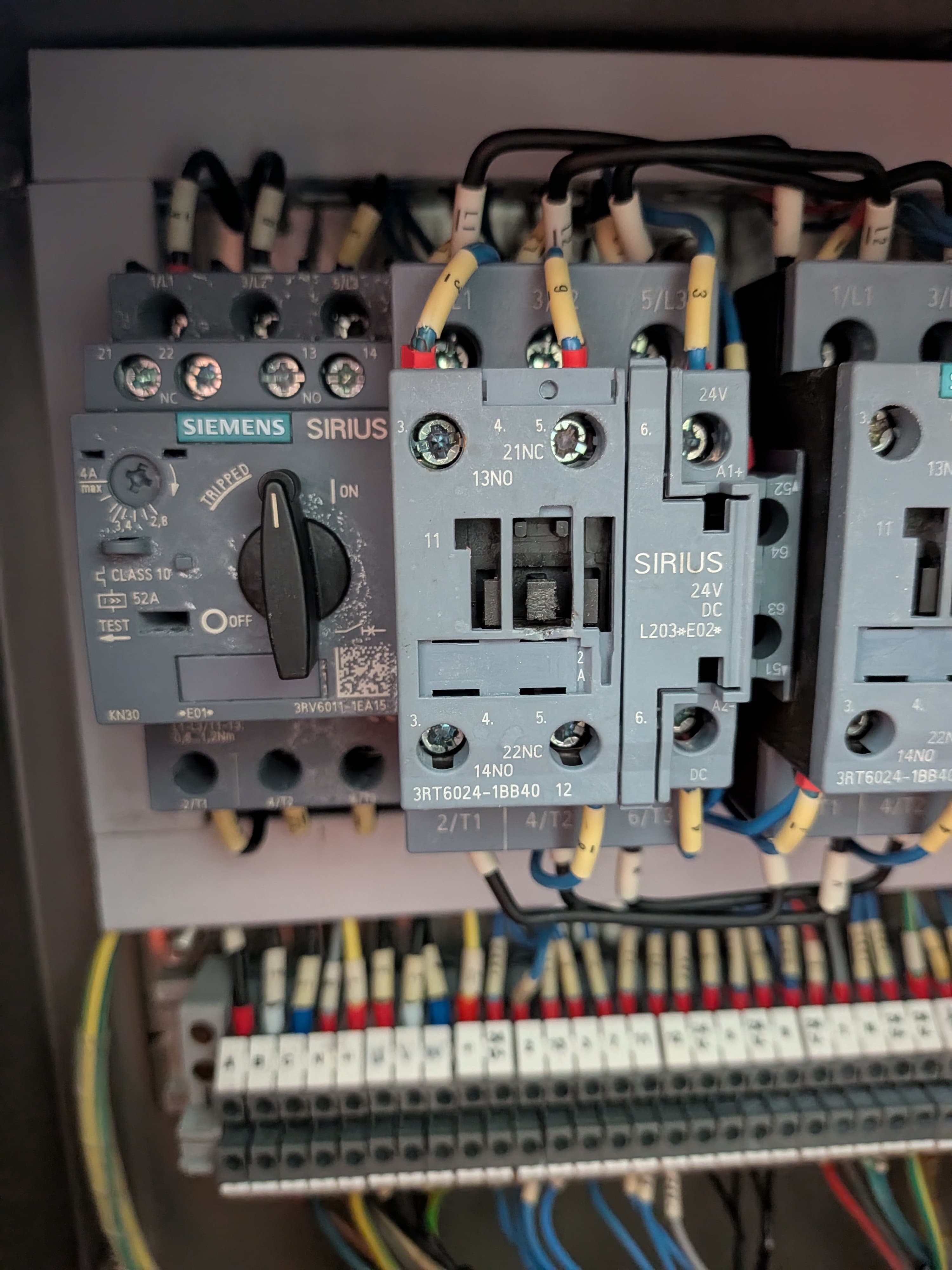
What it is
A contactor is a heavy-duty, remotely-operated switch. A small control signal energises its coil, and the coil's magnetic pull closes a set of main contacts that carry the load current.
It lets a low-power control circuit (a button, a PLC output, a timer) switch a high-power load safely and at a distance.
How it works
Energise the coil and it becomes an electromagnet, pulling the moving armature so the main contacts close. Remove the coil voltage and a spring snaps the contacts back open.
Most contactors also carry auxiliary contacts — small extra contacts (normally-open or normally-closed) used for seal-in latching, interlocks, and status feedback rather than load current.
Where it's used
Motor starters, heater banks, lighting contactors, and anywhere a control circuit needs to switch real power. They're rated by the current and duty they can switch and break.
Common faults: a coil that reads voltage but won't pull in, contacts that weld closed, chatter from low coil voltage, and auxiliary contacts that don't make for the seal-in.
What it looks like when it fails
Coils fail open — correct volts at A1–A2, no clunk, often a burnt smell — or develop shorted turns, which shows as humming, chattering, or a coil too hot to touch. Chatter also comes from low control voltage or a loose control connection: the coil can't hold the armature in cleanly.
Main contacts pit and burn until a pole stops conducting — the motor single-phases even though the contactor operates — or they weld shut so the load won't stop. Auxiliary contacts wear too: a seal-in aux that doesn't make is the classic 'runs while I hold the button' fault. Dust and gunge can jam the armature outright.
How to test it
Isolate and prove dead — control and power. For the coil, lift one coil lead and measure resistance across A1–A2: expect a definite reading (roughly hundreds of ohms for a 230 V coil, much less for 24 V — it varies by brand and frame size, so compare a known-good one). OL means an open coil; near zero means shorted turns.
Live, if you're licensed and it's safe to work that way: rated volts across A1–A2 with no pull-in condemns the coil or mechanism. Under load, measure the volt-drop across each closed main pole — a healthy pole drops a few millivolts; a pole reading hundreds of millivolts (or running hotter than its mates) is burnt inside.
Gotchas
Measure the coil across A1–A2, not A1 to earth — a floating reading can look healthy and means nothing. And lift a lead before ohming: parallel paths through the control circuit or interposing electronics will lie to you.
A 'clunk' proves the armature moved, not that power flows — burnt mains can be open on a contactor that operates perfectly. If it drops out with one pole welded, the motor doesn't stop clean; it single-phases and cooks. And match replacement coils on voltage AND type — 24 V AC and 24 V DC coils look identical on the shelf.
Safety first
A welded contactor can't switch its load off by normal means — isolate upstream. Treat the load side as live until proven dead.
Isolate, lock out / tag out, and prove dead before working unless a live test is specifically required, authorised, and carried out under proper supervision. Always follow local regulations, your site procedures, and the equipment manufacturer's documentation.
Related faults
Contactor has voltage at the coil but won't pull in
You measure the rated control voltage (e.g. 24V) across the coil terminals, but the contactor refuses to energise — no clunk, no pull-in, contacts stay open.
Contactor contacts welded closed — load won't switch off
The contactor won't drop out when the coil is de-energised. The load stays powered even with the control circuit off, because the main contacts have welded together.
Contactor chattering or buzzing instead of holding in
The contactor rapidly clicks/buzzes, pulls in and drops out repeatedly, or hums loudly without seating cleanly. Often comes with arcing noise and heat.
Auxiliary contact not making — seal-in or interlock fails
The contactor pulls in, but an auxiliary contact (used for seal-in, interlock, or status) doesn't change state, so the circuit won't latch, an interlock misbehaves, or status feedback is wrong.
Contactor drops out on its own / won't stay latched
The contactor pulls in when you press start but drops out the moment you release the button, or randomly during running — the seal-in (latch) isn't holding it.
Related definitions
Relay
A small electrically-operated switch — like a miniature contactor — used to switch or route control signals.
Overload relay
Protects a motor from sustained over-current by tripping the control circuit if it runs too hot for too long.
Start/stop circuit (seal-in)
A momentary start button that latches a contactor on, held by its own auxiliary contact until stop is pressed.
Transformer
Transfers electrical energy between circuits by magnetic coupling, stepping voltage up or down.