PLC (Programmable Logic Controller)
An industrial computer that reads inputs, runs a program, and drives outputs to control machinery.
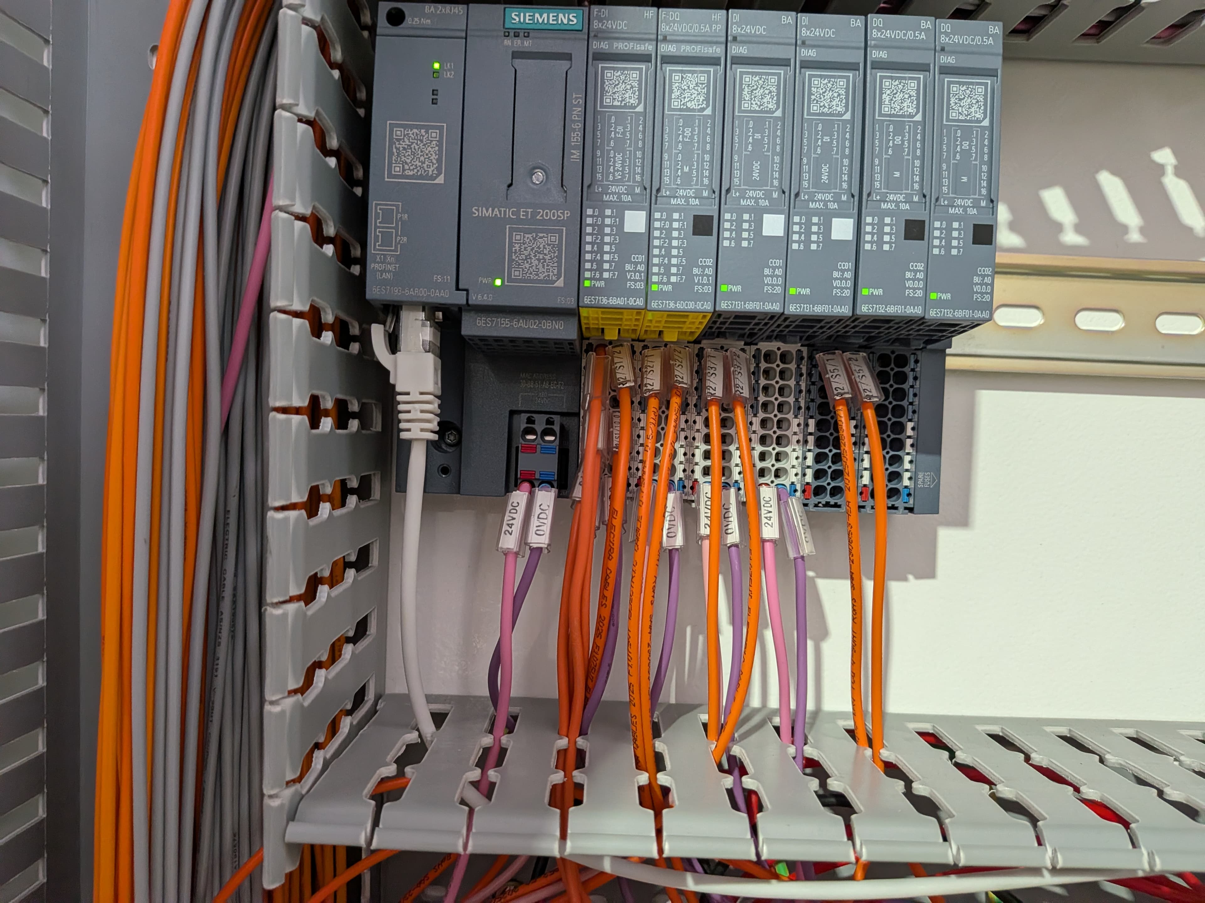
What it is
A PLC is a rugged industrial computer built to control machines and processes. It reads signals from the field, runs a stored program, and switches outputs to make things happen — reliably, in real time.
How it works
It runs a continuous scan: read all inputs, execute the program logic, then update all outputs — over and over, many times a second. Inputs come from sensors, switches, and signals; outputs drive contactors, valves, lamps, and drives.
An output's indicator LED follows the program's intention, not the physical output — which is why an output can show 'on' while the field device stays dead (a failed output, lost field supply, or broken wire).
Where it's used
Machine control, process plants, building services — anywhere sequenced or interlocked control is needed. I/O can be local or remote, often over a network.
Common faults: inputs not reading despite a signal present, outputs on but device dead, module faults, comms loss, and the controller dropping into a fault/stop state.
What it looks like when it fails
The PLC itself rarely dies; its edges do. Input side: a signal present at the terminal but the program never sees it (dead channel, wrong common, threshold issues). Output side: the program says on but the field device is dead — blown output transistor or relay, lost field supply, or a broken wire beyond the terminal.
Above that: module faults and rack errors, comms loss to remote I/O or the HMI, and the controller dropping to STOP/fault — which kills every output at once, not just one.
How to test it
Split the world at the terminal strip. Inputs: measure the signal at the input terminal itself — present there but no input LED / program bit means the PLC side; absent means the field side. Outputs: command the output on and measure at the output terminal — volts there means the fault is out in the field; nothing there means the card or its field supply.
Check the separate field supply and its fuse early — the card's own LEDs can run happily off the backplane while the field 24 V is gone, which looks exactly like 'everything on, nothing works'.
Gotchas
Output LEDs on many cards show the commanded logic state, not the real output — a blown channel can sit there glowing 'on' over a dead device. Trust the meter at the terminal, not the LED.
Forcing I/O bypasses the program's interlocks — machinery can move the instant you force. Clear it with whoever owns the machine, and remember a 'dead input' can also be a 2-wire sensor leaking just under the input's threshold.
Safety first
Forcing or returning a PLC to run can move machinery. Confirm the area is safe and back up the program before changes.
Isolate, lock out / tag out, and prove dead before working unless a live test is specifically required, authorised, and carried out under proper supervision. Always follow local regulations, your site procedures, and the equipment manufacturer's documentation.
Related faults
PLC input not reading despite a signal present
A field device is clearly providing a signal, but the PLC input bit/LED doesn't come on — the program never sees the input, so logic that depends on it won't run.
PLC output LED is on but the device doesn't work
The PLC output indicator says the output is energised, but the connected device (valve, contactor, lamp, motor starter) does nothing. The program thinks everything is fine.
PLC in fault / stop mode (not running the program)
The PLC has stopped running its program — a fault LED is on or it's in STOP/PROG mode — so no I/O is being controlled and the machine is dead in a defined way.
PLC communication fault (network / remote I/O)
The PLC has lost communication with a device, remote I/O, HMI, or network — comms-fault indication, missing data, or remote I/O dropping out.
Related definitions
Relay
A small electrically-operated switch — like a miniature contactor — used to switch or route control signals.
Proximity sensor
Detects the presence of a target without contact — inductive, capacitive, or photoelectric.
HMI (operator panel)
A touchscreen/operator interface that lets people monitor and control a machine or process.
Control vs power circuits
Low-power control logic decides what happens; the power circuit carries the load — kept separate for safety and clarity.